
This is a comprehensive, step-by-step guide for disassembling the PlayStation 3 Fat console CECHLxx with motherboard VER-001.
How to open the PS3 Fat, clean the dust, replace the thermal paste, CPU and GPU IHS Removal and replacing the CMOS Battery with this video:
PS3 Fat CECHLxx (VER-001) Deep Maintenance Guide. This comprehensive, highly detailed guide will walk you through the process of disassembling, cleaning, and replacing the thermal paste, removing the IHS from the Cell processor and RSX graphics processor (GPU), and of course replacing the CMOS Battery on the PlayStation 3 Fat. CECHLxx = CECHL01 CECHL02 CECHL03 CECHL04 etc.
You will need a Phillips #1 screwdriver, a Torx T8 Security screwdriver (with a center hole), 90%+ Isopropyl Alcohol (IPA), cotton swabs, and high-quality thermal paste (like Arctic MX-4).
Note: While the small components surrounding the processors use solid thermal pads, the core CPU (Cell) and GPU (RSX) processors require liquid thermal paste, which must be fully cleaned and replaced once opened.
------------------------------
Phase 1: Outer Shell & Hard Drive Disassembly
- Hard Drive Removal. Remove the HDD Cover: Locate the rectangular plastic cover on the side of the console. Insert a flathead screwdriver, nylon spudger, or your fingernail into the small indentation slot and pry the plastic cover outward. Unscrew the Bracket: Locate the single blue Phillips screw holding the internal metal hard drive bracket in place. Unscrew it completely (be careful not to strip it). Extract the HDD: Pull the small metal wire loop handle on the drive bracket outward, then slide and pull the hard drive straight out of the slot.
- Top Faceplate Removal. Locate the Hidden Screw: Look at the side of the console near the hard drive slot for a small rubber foot/cap covering a hidden chassis screw. Note that you may need to peel back a warranty sticker if it is still intact. Use a precision tweezer or a small flat blade to remove the rubber cap.
- Unscrew the Security Screw: Use a Torx T8 security screwdriver to remove the single hidden screw beneath that rubber cap.
- Slide the Faceplate: Place your palms flat on the glossy top faceplate (the decorative plate featuring the PlayStation 3 logo). Slide it horizontally toward the left until you hear or feel a click. Lift the faceplate straight off to expose the matte plastic inner cover.
- Inner Top Cover Removal Unscrew the Housing: Locate the 7 Phillips screws visible on the inner top cover. Keep track of their positions as you unscrew them all: note that one screw is significantly shorter than the rest. Keep them organized. Release the Plastic Clips: Move to the back right corner of the console's case. Carefully release the plastic locking clip holding the shell together. Lift the Top Cover: Keeping your hand on the clip, lift the top plastic cover straight up and clear from the bottom housing.
Phase 2: Internal Components & Power Block
- Power Supply Unit (PSU) Extraction. Disconnect Motherboard Cable: Locate the small white 4-pin connector cable traveling from the PSU to the motherboard. Firmly grip the plastic housing (not the wires) and pull it out. Disconnect AC Input: Move to the rear of the power supply. Unplug the black AC power connector block that connects the rear power socket to the PSU housing. Remove PSU Screws: Locate and remove the two Phillips screws securing the power supply unit. Note: These two screws are physically different from one another. Keep note of which goes where. Lift the PSU: Grab the sides of the PSU housing and pull straight up vertically. This requires a firm pull to disengage the unit from the two long metal prongs extending upwards from the motherboard assembly.
- Blu-ray Disc Drive Removal. Unclip Ribbon Cables: Gently locate the two cables attached to the optical disc drive. Flip up the black/brown locking tabs on the zero-insertion-force (ZIF) connectors to safely release and unclip the cables without tearing them. Remove the Drive: Lift the Blu-ray disc drive straight out of the chassis and set it aside.
Phase 3: Antennas, Shields & Core Disassembly
- Ground Wire & Fan Headers. Disconnect Ground Cable: Loosen and remove the single screw securing the green/copper ground connection wire directly to the main metal shield plate. Unplug the Fan: Locate the small 3-pin or 4-pin fan connector attached to the motherboard. Unplug it cleanly from its socket.
- Wireless Antenna Module. Unscrew the Module: Loosen the screw holding the wireless antenna board to the interior frame. Remove Wireless Assembly: Carefully lift the wireless antenna board out and disconnect the small, thin Wi-Fi antenna wire connectors from the board.
- Motherboard Shielding Strip-Down. Remove Perimeter Screws: Locate all remaining Phillips screws securing the large metal shield plate to the lower plastic bottom shell. Remove them all. Remove Chip Clamps: Locate the two spring-loaded metal retention clamps centered on the motherboard. These apply crucial downward pressure onto the Cell (CPU) and RSX (GPU) chips. Unscrew the four Phillips screws (two per clamp) evenly to avoid uneven tension on the silicon.Lift the Board Assembly: Carefully lift the complete motherboard and heatsink assembly out of the plastic bottom housing.
Phase 4: CPU & GPU Delidding (IHS Removal) & Deep Cleaning
- Clean Heatsink Surfaces: Remove the old thermal paste from the heatsink blocks. Use paper towels or a microfiber cloth soaked in high-purity isopropyl alcohol (IPA) to thoroughly dissolve and wipe away all dried paste residue.
- Delid the CPU (Cell) Integrated Heat Spreader (IHS): Use the Delid Tool V2 to separate the IHS from the CPU. Tip: While you can perform this without heating, you can warm up the IHS with a hair dryer beforehand to soften the adhesive and reduce cutting resistance.
- Clean CPU IHS: Remove all old thermal paste and silicone adhesive residue from the removed CPU IHS.
- Delid the GPU (RSX) Integrated Heat Spreader: Remove the IHS from the RSX chip using the specific RSX / GPU Delid Tool. Ensure the tool is positioned precisely as directed by the tool manufacturer to avoid scraping the silicon die or scratching the substrate traces.
- Replace CMOS Battery: Locate the CMOS battery on the board. If your PS3 has been resetting the system clock every time it is unplugged from the wall, take this opportunity to remove the old coin-cell battery and replace it with a fresh one.
- Clean GPU IHS Adhesive: Remove all old factory thermal paste and silicone residue from the removed GPU IHS.
- Clean GPU IHS Surface: Clean any remaining old thermal paste directly off the face of the RSX IHS.
- Prep Radiator Side of IHSs: Apply a fresh, thin, even layer of high-quality thermal paste to the top side of both IHSs (the surfaces that will sit directly against the heatsink radiator).
- Clean RSX Memory Chips: Carefully clean the memory chips surrounding the RSX die to remove any baked-on or burnt thermal paste residue. Proceed with extreme caution to avoid knocking off tiny surface-mount components.
- Apply Thermal Paste to Bare Chips: Apply a fresh, thin layer of thermal paste directly onto the bare, silver surfaces of both the delidded CPU and GPU dies, as well as onto the freshly cleaned GPU (RSX) memory chips.
- Clean Lower Shield & Cooler: Remove the lower metal shield, thoroughly clean the dust out of the cooling fan and heatsink fins, and re-install the lower metal shield.
- Inspect/Replace Thermal Pads: Inspect all thermal pads on the board components. If they are torn, hardened, or in bad condition, replace them with fresh thermal pads of the correct thickness.
- ⚠️ CRITICAL WARNING: Delidding (removing the Integrated Heat Spreader) carries a high risk of permanently destroying your CPU (Cell) or GPU (RSX) via scratched traces or cracked silicon. Proceed with extreme patience, using the proper tools.
- CELL (CPU) IHS Removal (Silicone Glue Cutting Method) For removing the IHS from the CELL processor, it is best to use a dedicated tool; I wouldn't experiment, to avoid damaging the CELL processor. In the video, I used the Delid Tool V2; I didn't use a heat gun on the CELL IHS, and it turned out fantastic. It probably would have been even easier if I had heated it up with a heat gun.
This video showing step by step how to removal IHS from CELL:
- Slide the tool into the side gap between the green substrate and the metal plate. Keep the tool perfectly flat and tilted slightly upward toward the metal lid to prevent digging into the underlying silicon traces. Work the Edges: Carefully cut through the rubber silicone adhesive along the edges. Once three of the four sides are sliced open, gently wedge and lift the tool to pop the CPU IHS off completely.
- RSX (GPU) IHS Removal (Silicon Epoxy Method)
The RSX IHS is held to the four memory modules surrounding the central chip by a rigid silicone adhesive, while the center core uses thermal paste.Apply Heat: Gently warm up the metal top of the RSX IHS using a heat gun for 30–45 seconds to soften the adhesive beneath. Insert the Tool: I used the RSX / GPU Delid Tool which you can see in the video clip.
This video showing step by step how to removal IHS from RSX:
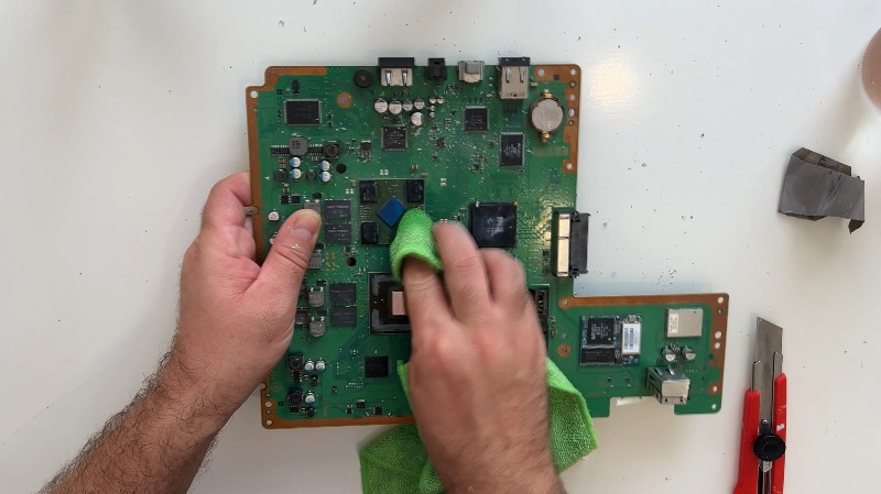
- Thermal Paste Cleanup Clean Die and IHS: Take workshop towels, microfiber cloths, or cotton pads dipped in 99% Isopropyl Alcohol (IPA). Wipe away all old, crusty, dried-out thermal factory paste from the bare CPU and GPU silicon dies. Clean the underside of both detached IHS plates. Wipe until the surfaces shine like mirrors. Očistite blokove hladnjaka: Očistite kontakt na masivnom aluminijskom nizu hladnjaka.
- Under-IHS Repasting. Apply a tiny, rice-grain-sized drop of premium non-conductive thermal paste (e.g., Arctic MX-4 or Noctua NT-H1) directly onto the bare, shiny internal silicon dies of both the CELL and RSX.
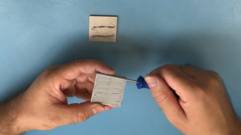
- Outer-IHS Repasting. Apply new thermal paste to the IHSs on the sides adjacent to the radiator. Apply a thin layer of thermal paste to the IHSs.Place the IHS on the heatsink and press them down to squeeze out the excess thermal paste. Place the IHS on the heatsink as precisely as possible, so that it fits the CPU and GPU as precisely as possible.
Phase 6: Reassembly
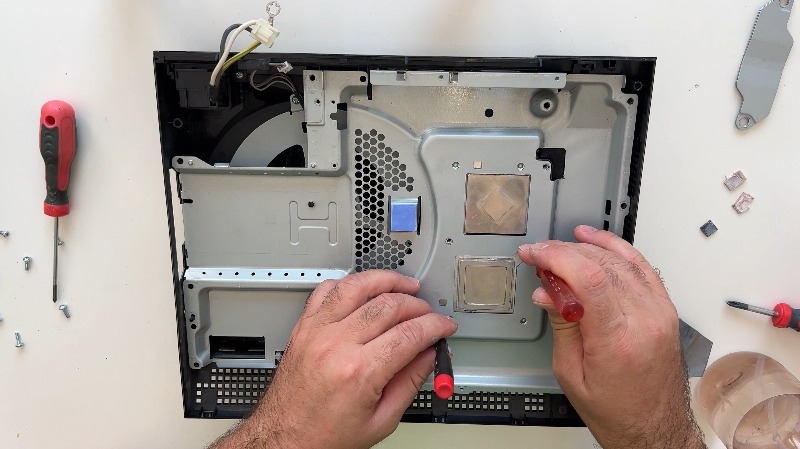
- Seat IHSs to Heatsink: Place the prepared IHSs onto the heatsink blocks and press them down firmly to squeeze out excess thermal paste and create a solid bond.
- Align IHSs Precisely: Ensure the IHSs are sitting as perfectly and precisely as possible on the heatsink so they line up flawlessly with the CPU and GPU dies during board installation.
- Final Thermal Pad Check: Double-check that all thermal pads are perfectly positioned before installing the motherboard.
- Re-seat the Motherboard: Carefully align and lay the motherboard back down onto the metal plate framework. Ensure the freshly pasted, bare processor dies match up perfectly with the pre-placed IHS blocks on the heatsink without smearing or wiping away the paste.
- Install Top Motherboard Shield: Place the main metal shield back over the top of the re-seated motherboard.
- Anchor the Shield: Tighten the first two screws that secure the shield assembly directly to the motherboard layout.
- Install and Tension Clamps: Place the two curved metal retention clamps over the CPU and GPU areas. Tighten their four screws gradually and alternately (turn one screw a few times, then switch to the other) to ensure flat, perfectly balanced pressure across the delicate silicon surfaces.
- Secure All Shield Screws: Tighten all remaining screws that secure the protective plate framework to the motherboard assembly.
- Re-install HDD Shield: Install the metal shield plate back over the hard drive bay area.
- Reconnect Wi-Fi/Wireless Antenna: Secure the wireless antenna by tightening its mounting screw, then firmly reconnect the small Wi-Fi antenna cable connector.
- Re-install Optical Drive: Reinsert the optical disc drive back into its designated bay within the case. Firmly reconnect its two data and power cables back to the motherboard.
- Reconnect Cooling Fan: Plug the cooling fan power connector back into its slot on the motherboard.
- Secure Ground Wire: Tighten the grounding screw along with its green/bare ground wire near the power connector area.
- Reinsert the Power Supply Unit: Align the two female terminal sockets underneath the PSU block with the vertical metal prongs in the console. Slide the PSU completely down onto these pins until it sits flush and flat inside the chassis cavity.
- Secure the PSU (Part 1): Firmly tighten the first two specific screws holding the power supply unit in place.
- Reconnect Motherboard-PSU Cable: Connect the white cable with the 4-pin connector from the power supply directly back into the motherboard.
- Secure the PSU (Part 2): Firmly tighten the remaining two screws to completely lock the power supply unit down.
- Reconnect AC Block: Plug the AC power connector block back into the rear of the power supply unit.
- Install Inner Top Cover: Place the inner plastic top cover back onto the console chassis.
- Drop in Housing Screws: Place all mounting screws back into their respective holes. Pay close attention to place the single short screw (labeled "S") into its correct designated slot.
- Tighten Housing Screws:Securely tighten all 7 screws on the inner top cover.
- Lock Top Faceplate: Place the glossy outer faceplate flat onto the console, slightly offset to the left, and push it horizontally to the right until it clicks firmly into place.
- Install Security Screw: Tighten the single Torx T8 security screw on the side of the console frame.
- Replace Rubber Plug: Pop the small rubber cap back into place to hide the security screw.
- Insert Hard Drive: Slide the hard drive bracket assembly straight back into its inner slot.
- Secure Hard Drive: Tighten the single blue Phillips screw to secure the hard drive bracket assembly to the system chassis frame.
- Snap HDD Cover: Snap the plastic hard drive bay cover back onto the outer shell. Reassembly is complete.