
PlayStation 3 Super Slim (CECH-4304C) Service Manual Cleaning, Thermal Paste Application, and Assembly Guide
This manual provides step-by-step instructions to completely disassemble, clean, repaste, and reassemble your PlayStation 3 Super Slim console.
Learn how to open the PS3 Super Slim, clean the dust, replace the thermal pad and close the console with this video:
PlayStation 3 Super Slim: Ultimate Deep-Clean & Thermal Paste Overhaul Disassembly Guide. This comprehensive, highly detailed walkthrough will guide you through the process of stripping down, cleaning, and replacing the thermal paste on your PlayStation 3 Super Slim.
You will need a Phillips #1 screwdriver, a Torx T8 Security screwdriver (with a center hole), 90%+ Isopropyl Alcohol (IPA), cotton swabs, and high-quality thermal paste (like Arctic MX-4).
Note: While the small components surrounding the processors use solid thermal pads, the core CPU (Cell) and GPU (RSX) processors require liquid thermal paste, which must be fully cleaned and replaced once opened.
------------------------------
Part 1: Outer Shell & Drive Extraction
- Release the Disc Drive Locks. Locate the top section of the console near the optical disc drive slide track. Remove the two Torx T8 security screws that secure the sliding top mechanism. Set them aside safely, as security screws are easy to strip if mishandled.
- Strip the Side Panel. Position your hands on the plastic side panel cover located on the right side of the console (when facing the front). Slide the cover firmly toward the back of the console to unlatch its plastic clips, then pop it completely off to expose the underlying chassis.
- Free the Hard Drive Bracket. Look into the newly exposed side cavity to find the hard drive bay. Unscrew the single blue Phillips screw that anchors the internal hard drive bracket to the main chassis frame.
- Extract the Storage Drive. Grip the metal pull tab on the hard drive caddy and pull the drive straight out of its slot. Store the hard drive in an anti-static environment away from magnets and dust.
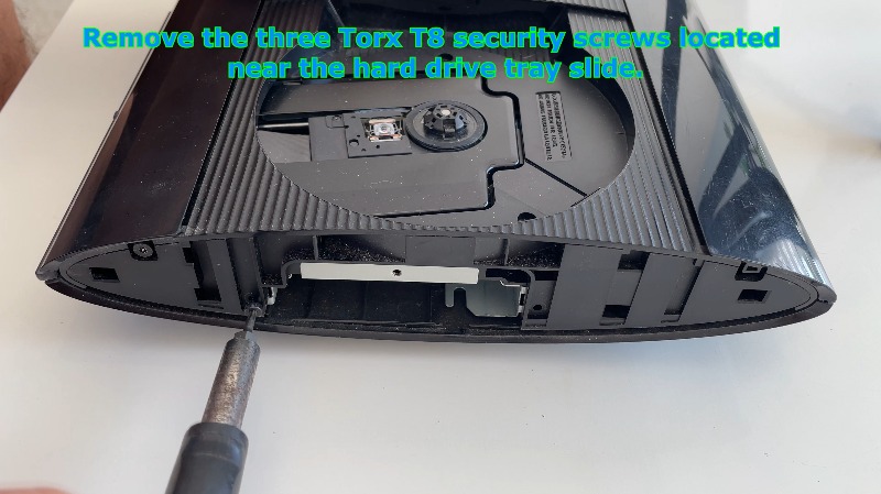
- Clear the Slider Screws. Return to the exposed side area near the hard drive tray slide track. Remove the three Torx T8 security screws holding this foundational frame piece together.
- Pop the Rear Finisher Trim. Locate the decorative plastic finisher trim piece at the rear top edge of the console. Use a flat-head screwdriver to gently depress the locking tab, then lift up to snap the finisher free from its housing.
- Pop the Front Finisher Trim. Move to the front edge of the console and locate the corresponding upper finishing element. Repeat the exact same process—depress the plastic locking tab with your flat tool and lift up to remove it.
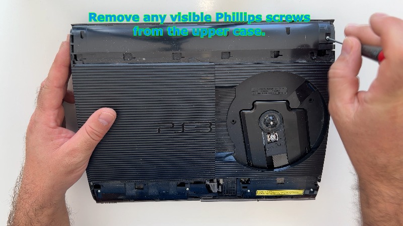
- Top Case Perimeter Screws. Inspect the newly exposed top surfaces where the finishers used to sit. Identify and remove all visible Phillips screws securing the upper case plastic shell to the inner metal frame.
- Flip the Console Upside Down. Carefully flip the console completely upside down onto a soft surface (like a microfiber towel) to protect the plastic from scratches.
- Uncover Hidden Bottom Screws. Locate the rubber feet and plastic screw covers scattered across the bottom shell. Pry off these rubber feet and screw covers using a flat prying tool or a guitar pick to reveal the deep screw wells below.
- Break the Warranty Seal. Locate the factory warranty sticker on the bottom casing. Peel off the warranty sticker completely to expose the final hidden security/Phillips screw underneath.
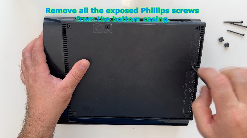
- Empty the Bottom Casing Screws. With all wells now exposed, remove all the Phillips screws located across the bottom casing of the console.
- Separate the Outer Shell. Flip the unit back right-side up. Gently pry around the seam of the top plastic cover and lift it straight away from the inner metal chassis, exposing the primary internal components.
Part 2: Internal Component Stripping
- Disconnect Motherboard Main Power. Locate the heavy, white electrical cable connector plugging directly into the motherboard surface. Carefully disconnect this main white cable connector by gripping the plastic housing firmly (do not pull the wires) and pulling straight up.
- Unbolt the Power Supply Unit (PSU). Identify the rectangular Power Supply Unit block. Unscrew the two long Phillips screws that deeply anchor the PSU down through the internal shielding.
- Evict the PSU. Grasp the PSU firmly on both sides and pull the PSU straight up and out of the console. Be mindful of the twin metal prongs underneath that it sits upon.
- Evacuate the Disc Drive. Locate the optical disc drive assembly. Carefully unclip all ribbon cables connecting the drive to the motherboard by flipping up their locking gates, then lift the disc drive entirely out of the chassis.
- Unplug the Fan Power. Find the small, thin wire bundle traveling from the cooling fan motor to the motherboard. Unplug this small fan connector from its socket on the board.
- Unbolt the Main Metal Shielding. Locate the remaining Phillips screws securing the sprawling outer metal shield assembly to the bottom plastic tub. Unscrew all of these perimeter screws to free the metal core.
- Disconnect the Power Button Ribbon. Locate the thin, delicate ribbon cable running from the front power button board to the mainboard. Unplug this ribbon cable carefully to prevent tearing the fragile traces.
- Free the Internal Core. Grasp the metal framework securely and lift the entire structural metal case assembly straight up and out of the lower plastic outer shell.
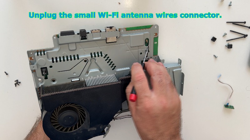
- Unplug the Wireless Antennas. Locate the small, coaxial Wi-Fi/Bluetooth antenna wires snapped onto the motherboard. Carefully pop off these small Wi-Fi antenna wire connectors from their gold-rimmed terminals.
- Flip for Shielding Disassembly. Take the isolated metal core assembly and flip it over onto its back to gain clear access to the motherboard shielding tray screws.
- Release the Heatsink Clamps. Locate the internal shield plate screws. Remove the 6 screws securing the shield plate, paying extreme attention to the two heavy-duty heatsink clamp screws that dictate the pressure over the main processing chips.
- Lift the Metal Shield. Carefully lift the metal shield plate away from the motherboard surface, ensuring it does not snag on any small surface-mounted components.
- Inspect and Manage Thermal Pads. Locate the small, gummy thermal pads resting on the RAM chips or voltage regulators. Take great care of these thermal pads so they don't get lost; if they are brittle, crumbling, or heavily contaminated with dust, replace them with fresh thermal pads of identical thickness.
- Break the Thermal Paste Bond. Gently lift the motherboard off the main metal cooling plating. Warning: You will likely feel immense resistance because the factory thermal paste has dried into a concrete-like glue. Do not force it; pry lightly and uniformly on the edges of the board until the suction frees itself.
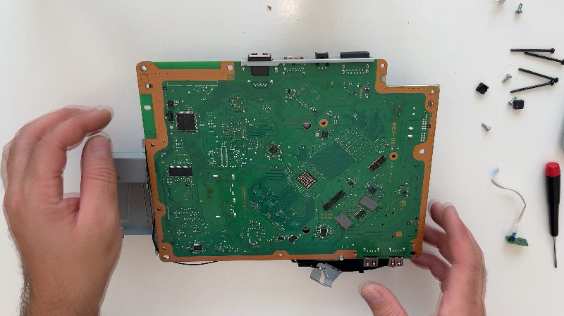
Part 3: Deep Cleaning & Thermal Restoration
- Inspect the RSX Heatsink. Locate the integrated copper plate attached to the heatsink framework. This small copper plate serves as the dedicated heatsink for the graphics processor (RSX), sitting directly flush against it to pull away intense operational heat.
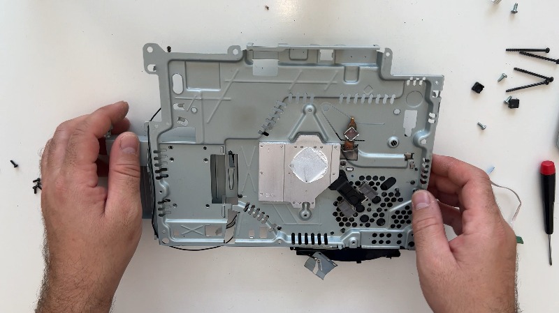
- Strip Old Paste from the Heatsink. Remove the old, crusty thermal paste from the heatsink surfaces using paper towels or a microfiber cloth generously soaked in high-concentration (90%+) isopropyl alcohol. Thoroughly scrub the mating surfaces until all dried residue is completely gone.
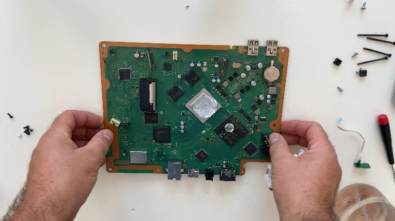
- Polish the Copper Heatsink (Optional). If you notice that the copper block has oxidized, tarnished, or turned black over years of heat cycles, you can choose to gently polish the copper refrigerator block using a fine abrasive or metal cleaner to restore its bright, raw copper finish for optimal thermal transfer.
- Clean Polished Residue. If you performed the previous optional step, thoroughly clean the polished metal parts with fresh paper towels or a microfiber cloth soaked in pure isopropyl alcohol to ensure zero chemical polishing residue remains.
- Repeat Copper Polish Check (Optional). Inspect the copper elements one more time. If any deep oxidation or black spots remain on the mating surfaces, give the copper refrigerator block an additional gentle polish to achieve a completely smooth, mirror-like contact zone.
- Final Wipe of Polished Components. Thoroughly clean the polished metal components once more using pure isopropyl alcohol and a clean microfiber cloth to ensure a sterile surface for the new thermal compound.
- Strip Old Paste from the Processors. Move your attention to the bare motherboard. Remove the old thermal paste from both the CPU (Cell Broadband Engine) and the GPU (RSX) using paper towels or a microfiber cloth soaked in isopropyl alcohol. Clean them thoroughly until the metal integrated heat spreaders (IHS) are pristine and the printed text on the chips is clearly visible.
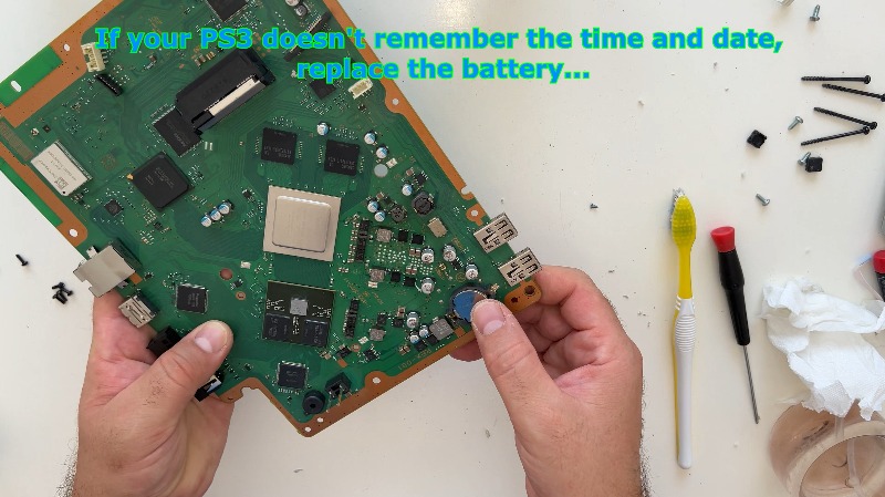
- Check the CMOS Battery. Inspect the coin-cell CR2032 battery snapped into the motherboard. If your PS3 has been failing to remember the correct time, date, or network settings every time you unplug it, take this opportunity to pop out the old battery and replace it with a fresh one.
- Disassemble the Fan Air Deflector. Move over to the standalone cooling fan housing. Locate and remove the two screws holding the plastic air deflector shroud to the fan body, then lift the deflector away.
- Unroute the Antenna Wires. Locate the long, thin wireless antenna cables snaking around the fan shroud. Gently pull out the cables for the wireless antennas from their molded plastic routing channels.
- Remove the Cooling Fan. Locate the final retaining screw holding the fan motor down. Remove the screw that holds the fan assembly and lift the fan completely out of its plastic housing.
- Blast the Dust Away. Take the bare fan assembly and the metal heatsink fins to a well-ventilated area. Use a soft-bristled brush or a can of compressed air to clear out all built-up dust bunnies and debris packed deep inside the cooling fan blades and between the dense aluminum heatsink fins.
- Reinstall the Clean Fan. Drop the clean fan back down into its designated mounting position and reinsert the fan retaining screw, tightening it securely.
- Reassemble the Shroud & Route Cables.
Place the plastic air deflector shroud back onto the fan body, and carefully place the thin wireless antenna cables back into their designated plastic housing tracks. - Secure the Air Deflector. Locate the two small screws removed in Step 9 and tighten them back down onto the fan air deflector to lock the shroud assembly together.
- Apply Fresh Thermal Paste (Center Dot Method). Grab your premium replacement thermal paste syringe. Apply a pea-sized dot of new thermal paste directly onto the exact center of both the CPU (Cell) and GPU (RSX) metal heat spreaders.
- Spread the Thermal Paste (Optional alternative). If you prefer total manual coverage, you can use a plastic spatula or a gloved finger to spread a thin, perfectly flat, uniform layer of thermal paste over the entire surface area of the CPU die.
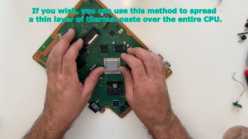
- Match Paste to the RSX Heatsink. To guarantee zero air gaps on the graphics side, apply a complementary thin layer of thermal paste directly onto the copper contact pad of the RSX graphics card's heatsink assembly.
Part 4: Systematic Reassembly
- Set the Motherboard Down. Carefully align and lay the motherboard back down onto the metal plate framework, ensuring the freshly pasted processor dies match up perfectly with the corresponding heatsink blocks without smearing the paste.
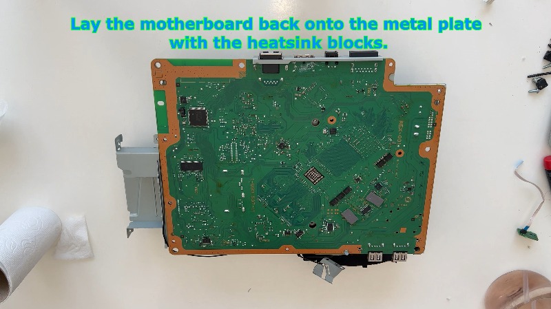
- Reinstall the Metal Backing Plate. Lower the structural metal backing plate back down over the top side of the flipped motherboard assembly.
- Torque the Heatsink Clamps. Locate the two spring-loaded heatsink clamp screws. Tighten the two heatsink clamp screws gradually and alternatingly (a few turns on one, then a few turns on the other) to ensure perfectly flat, even pressure across the processor silicon.
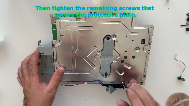
- Fasten Remaining Shield Screws. With the core clamps locked down, tighten the remaining four screws that secure the protective shield plate to the motherboard assembly.
- Route the Wi-Fi Cables. Route the thin Wi-Fi/Bluetooth antenna wires smoothly back into their integrated routing channels along the metal frame to prevent them from getting pinched during final shell closure.
- Plug in the Fan Motor. Locate the small fan power lead and connect the fan connector securely back into its motherboard socket.
- Seat Assembly in Bottom Case. Pick up the consolidated metal core structure and lay the entire assembly back down into the lower plastic console housing, aligning the back I/O ports with the rear cutouts.
- Secure Core to Lower Casing. Locate the perimeter chassis screws and tighten the remaining Phillips screws securing the outer metal shield assembly to the lower plastic housing.
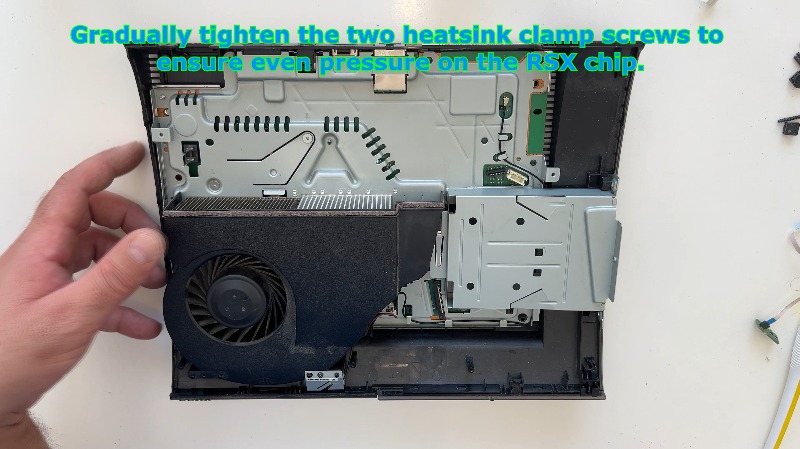
- Final Check on RSX Clamp Pressure. Double-check the tension over the graphics processing unit by gradually tightening the two heatsink clamp screws once more to ensure absolute, rock-solid even pressure on the RSX chip.
- Reconnect the Power Ribbon. Take the front control panel's thin ribbon cable and connect it back to the dedicated motherboard terminal, flipping down the latch to lock it in place.
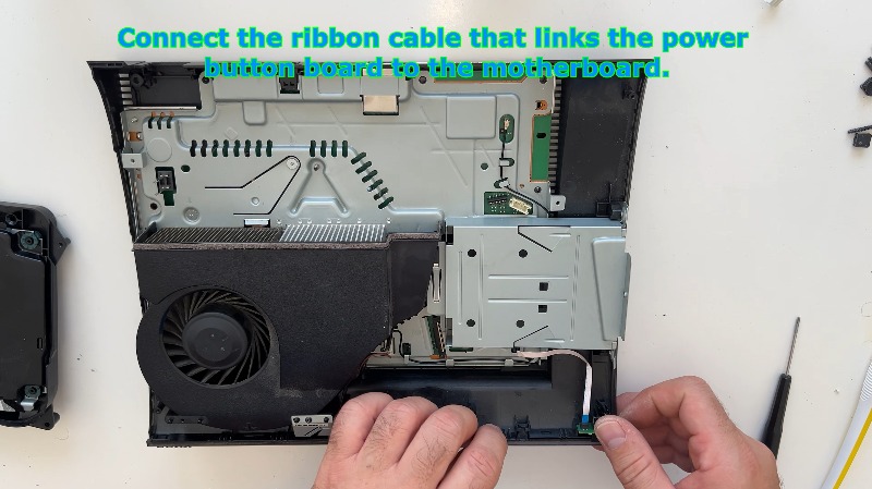
- Mount the Optical Drive (Ribbons). Bring the optical disc drive back to the chassis. Connect all ribbon cables associated with the optical drive back into their respective motherboard sockets, ensuring they are seated deeply before locking them down.
- Connect Internal Board Power. Connect the primary internal power supply distribution cable back into the motherboard socket securely.
- Double Check Optical Drive Cables. Perform a quick safety inspection of the disc drive alignment and ensure all ribbon cables connected to the optical drive are fully secure and lie flat without kinks.
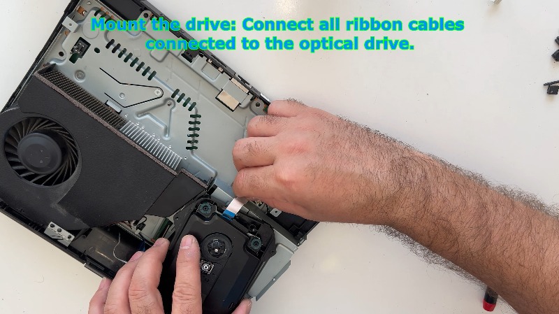
- Reinsert the Power Supply Unit. Take the PSU block and line up the two female terminal sockets underneath it. Reinsert the Power Supply Unit, making absolutely sure it slides completely down onto its dual vertical metal pins before pushing it flat into the chassis cavity.
- Connect PSU to Motherboard Cable. Take the small wiring harness running from the PSU and connect the cable securely between the motherboard and the power supply unit.
- Bolt Down the PSU. Locate the long, specialized screws and tighten the two screws that hold the power supply unit down firmly into the chassis.
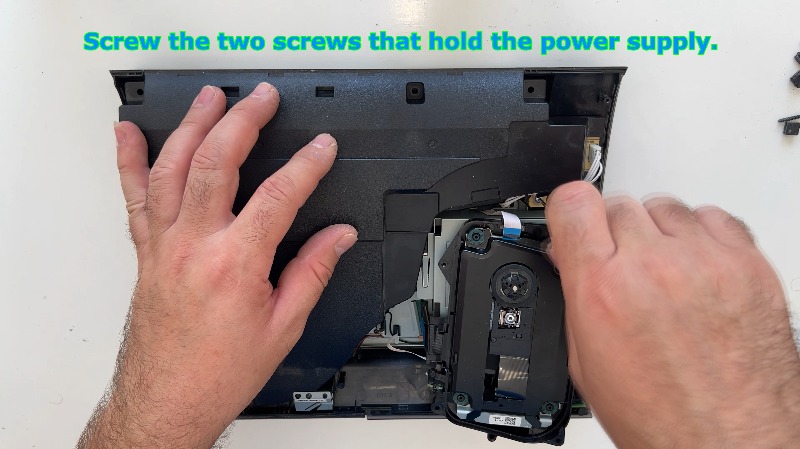
- Align the Top Cover. Take the large, main plastic top shell and carefully place the top plastic cover down over the reconstructed inner chassis, ensuring all edges line up seamlessly.
- Fasten the Top Cover Screws. Locate the perimeter casing screws and tighten all screws holding the top cover down into the structural internal metal frames.
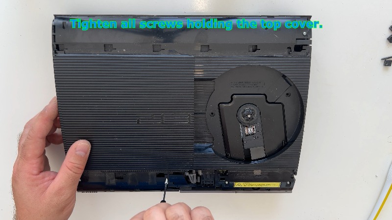
- Lock the Drive Track Screws. Go back to the sliding disc door track assembly and tighten the two Torx T8 security screws located on the drive track frame.
- Flip the Console Over Once More. Flip the console completely upside down onto your soft protective surface to button up the bottom plate.
- Fasten Bottom Casing Screws. Locate all the remaining long and short perimeter casing screws and tighten all visible Phillips screws on the lower case housing.
- Replace Foot Covers. Take your rubber pads and plastic caps and reinstall the rubber feet and screw caps back into their respective wells to hide the screw heads.
- Clean the Warranty Area. Using a small drop of isopropyl alcohol, clean away the sticky remnants or residue left behind by the broken factory warranty sticker for a clean aesthetic.
- Flip the Unit Right-Side Up. Carefully flip the fully assembled console back right-side up onto its brand-new clean rubber feet.
- Clean the Top Surface. Take a fresh microfiber cloth and thoroughly wipe down and clean the top plastic cover to clear away any fingerprints or leftover thermal paste smudges from disassembly.
- Snap the Rear Trim On. Take the rear decorative trim strip and place the rear plastic cover finisher back into position, pressing down firmly until you hear the plastic tabs click into place.
- Snap the Front Trim On. Grab the front decorative trim strip and place the front plastic cover finisher back into position, applying uniform pressure until it snaps securely shut.
- Secure the Slider Tracking. Locate the final side security screw points and tighten the three Torx T8 security screws located near the hard drive tray slide mechanism.
- Insert the Storage Caddy. Take your hard drive enclosure assembly and slide the disc caddy straight back into its internal bay storage slot until you feel the SATA connectors interface perfectly.
- Lock the Hard Drive. Locate your specialized blue fastener and tighten the single blue Phillips screw that locks the hard drive bracket assembly into the system frame.
- Reinstall the Outer Beauty Panel. Take the large right-side plastic panel skin, align the plastic guide hooks into the side of the console chassis, and slide the plastic side cover forward onto the console until it locks flush with the surrounding trim.
---