
Here is a detailed, step-by-step guide for repairing damaged firmware on a Silicon Motion SM2258XT SM2259XT or SM2259XT2G SSD Controller.
⚠️ Important Prerequisites & Warnings
Data Loss Warning: This process involves a complete factory reset and low-level formatting. All data on the SSD will be permanently deleted.
Hardware Needed: A USB-to-SATA adapter, a computer, and a small metal tool (like a paperclip or tweezers) to short the jumper pins.
Software Needed: SMI Flash ID Reader and the correct version of SMI MPTool matching your specific NAND flash memory.
The SSDs I used had the following specifications:
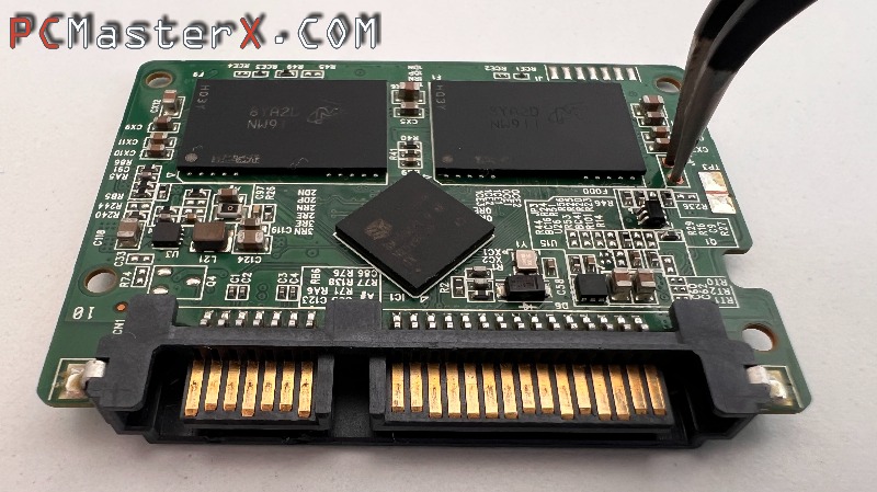 |
| Crucial BX500 120GB |
| SM2258XT |
| Micron 64L(B16A) TLC 256Gb/CE 256Gb/die |
| SM2258XT_B17A_PKGR0605A_FWQ0816C0_FWR0522A0_B16A |
| https://www.usbdev.ru/files/smi/sm2258xtmptool/ |
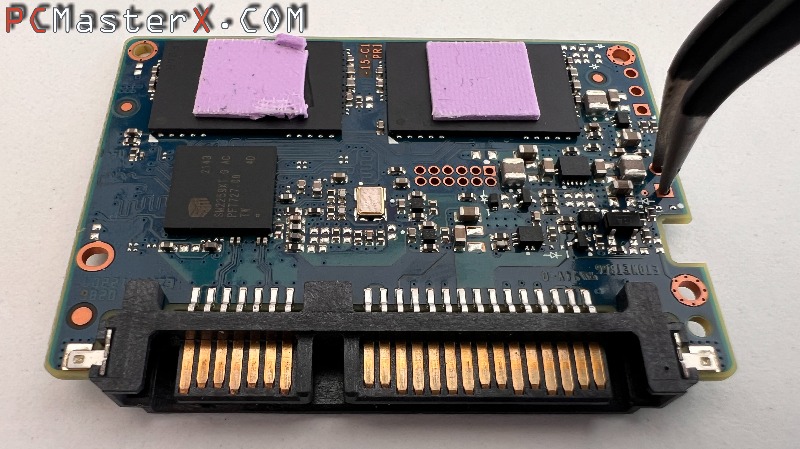 |
| Crucial BX500 240GB |
| SM2259XT |
| Micron 176L(B47R) TLC 512Gb/CE 512Gb/die |
| IMB47 FIMB47R SM2259XT(AC)_FIMB47R_PKGU0524A_FWU0524A0 |
| https://www.usbdev.ru/files/smi/sm2259xtmptool/ |
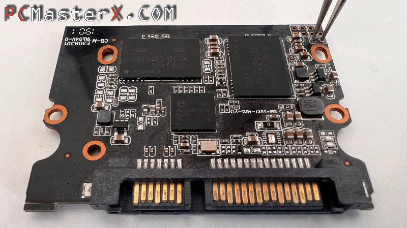 |
| No Name 120G |
| SM2258XT |
| Hynix 3dv4-72L TLC 8k 512Gb/CE 512Gb/die |
| SM2258XT(AD)_HY3D-V4_PKGU0105A_FWT1130A0 |
| https://www.usbdev.ru/files/smi/sm2258xtmptool/ |
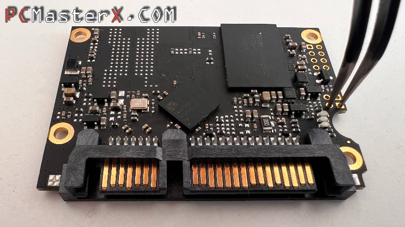 |
| Intenso TOP 128GB |
| SM2259XT2G |
| SDUNEIAMA-064GCE |
| Sandisk,512Gbit,SDUNCIAMA-064GB(bics5)(SM2259XT2) |
| BiCS5 SM2259XT2_FBiCS5_PKGV0415B_FWV0414A0 |
| https://www.usbdev.ru/files/smi/sm2259xt2mptool/ |
The archives are grouped and titled using specific naming templates. You must match your NAND generation tag to the folder/zip text:
Example 1: SMI MPTool SM2258XT_B17A_PKGR0605A_FWQ0816C0_FWR0522A0_B16A.rar
B16A = Micron 176L(B47R) TLC 512Gb/CE 512Gb/die
Example 2: SM2258XT(AD)_HY3D-V4_PKGU0105A_FWT1130A0.rar
HY3D-V4 = Hynix 3dv4-72L TLC 8k 512Gb/CE 512Gb/die
Step 1: Force the SSD into "ROM/Flash" Mode Because the firmware is corrupted, you must bypass the standard boot cycle to let the mass production tool communicate with the controller.
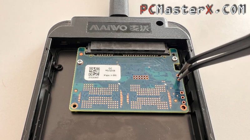
- Locate the jumper pins: Open the SSD casing and look for two small, unpopulated solder pads or pins labeled "ROM" or "JP1/JP2" on the PCB.
- Short the jumper: Use a paperclip or tweezers to bridge (connect) these two pins together.
- Connect to the PC: While holding the jumper shorted, plug the SSD into your computer using the USB-to-SATA adapter.
- Release the jumper: Wait exactly 3 seconds, then remove the paperclip/tweezers.
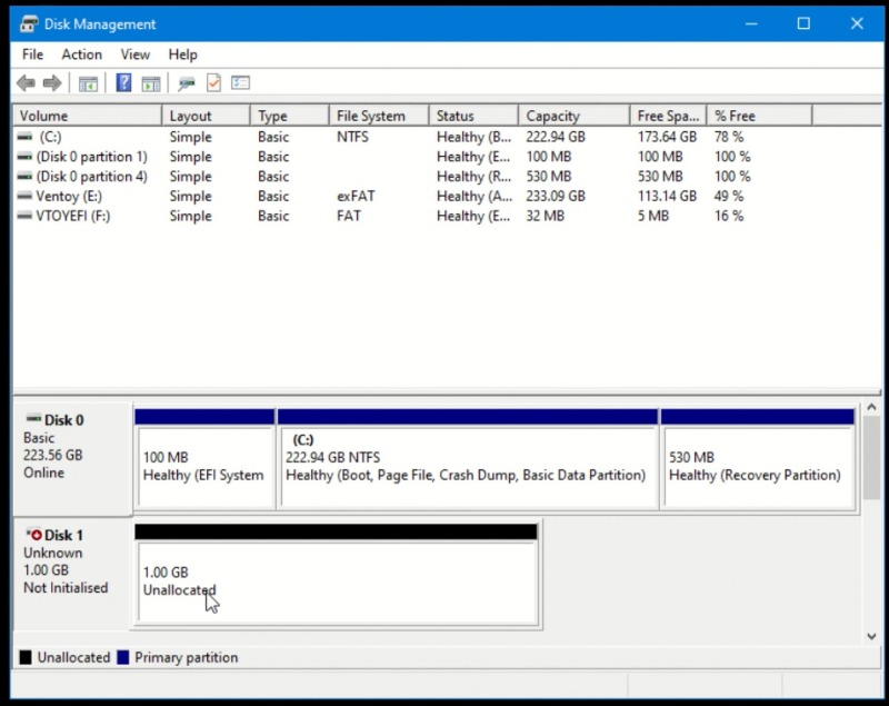
- Verify in Disk Management: Open Windows Disk Management (diskmgmt.msc). The drive should now be recognized as a 1 GB disk (generic Silicon Motion ROM mode). If it doesn't appear, unplug it and retry the timing.
Step 2: Identify the NAND Flash Memory You cannot flash the firmware blindly; the software must match the exact flash memory chips inside your drive.
- Open the SMI Flash ID Reader utility.
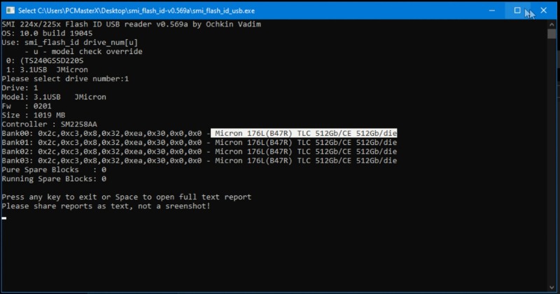
- Select the drive letter or target number corresponding to your 1GB USB-connected SSD.
- Run the program. It will output a text log detailing the exact manufacturer and part number of your memory chips (e.g., Intel, Samsung, SanDisk, or Micron MLC/TLC). Download the exact MPTool: Look online (sites like USBDev or FlashBoot) for the specific version of SMI MPTool that explicitly supports the flash ID found by the reader.
Step 3: Configure the SMI MPTool
- Launch the SMI MPTool application.
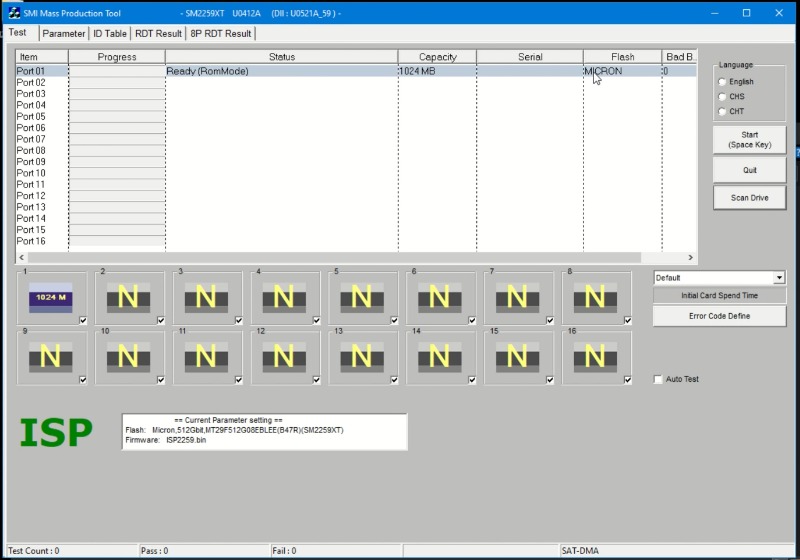
- Click the Scan Drive button. The software should detect your SSD on its designated port.
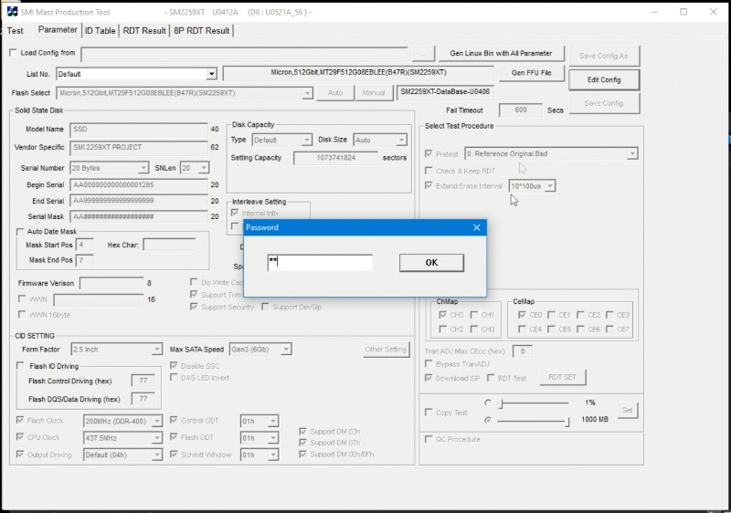
- Navigate to the Parameter tab at the top.
- When prompted for a password, press the Spacebar twice (" ") and hit Enter to unlock editing mode.
- Configure the parameters:
Flash Type: Select the manual option matching the exact memory chip ID you found in Step 2 (or choose Auto if your specific package version supports it reliably).
SSD Name / Model String: You can customize the name of the SSD here (this is the name that will show up in Device Manager).
Capacities / Disk Size: You can leave it on auto or adjust and set the memory size to match the original factory capacity of your SSD. 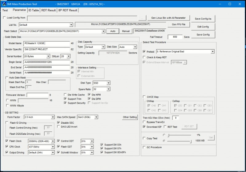
- Click Save (or Save Config) and return to the main Test page.
Step 4: Flash the Firmware
- Confirm once more that the target drive listed in the tool is your connected USB SSD.
- Click the Start button
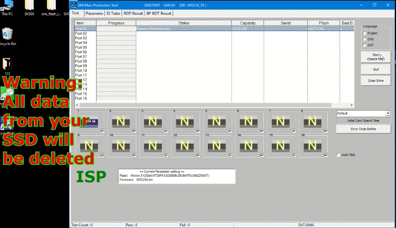
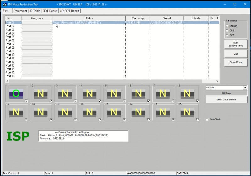
- Do not disconnect the drive. Wait for the progress bar to complete. When successful, the status box next to the drive will turn Green and display "PASS".
- Close the SMI MPTool software.
Step 5: Initialize, Format, and Test the Drive
- Power cycle the drive: Unplug the USB-to-SATA adapter from the computer, wait a few seconds, and plug it back in. This forces the controller to boot into its new, working firmware.
- Format the SSD: Open Windows Disk Management. The system will prompt you to initialize the disk (choose MBR or GPT). Right-click the unallocated space, select New Simple Volume, and format it using the NTFS or exFAT file system.
- Basic Verification: Perform a quick manual test by creating a new folder on the drive, pasting a few files into it, and deleting them to verify read/write capabilities.
- Advanced Performance Diagnostics (Recommended): To ensure long-term stability and catch bad blocks, test the SSD using professional utilities:
CrystalDiskMark: To verify read/write speeds match manufacturer specs.
CrystalDiskInfo: To monitor the health status and S.M.A.R.T. attributes.
Step 6: Reassembly
Once all software tests pass successfully, safely eject the USB adapter, disconnect the SSD, and mount the PCB securely back inside its original physical housing. Your SSD is now fully restored and ready for internal installation. If you run into errors during this process, let me know:
Step 5: Initialization
Reconnect: Plug the SSD back into your computer normally. Format: Use Disk Management to initialize the disk (GPT/MBR) and create a new partition. Your SSD is now repaired and ready for use.